Choosing high temperature pressure sensors is not a simple matter of selecting the highest temperature rating. The right device must survive heat, pressure cycles, vibration, chemical exposure, and installation stress. A sensor rated for 600°C may still fail early if its diaphragm material reacts with the process medium. Small details matter.
Lord Kelvin’s well-known principle remains highly relevant: “If you cannot measure it, you cannot improve it.” For high temperature applications, measurement quality depends on more than accuracy at room temperature. Engineers should examine operating temperature, pressure range, overload capacity, accuracy drift, response time, electrical output, and calibration stability. Remote diaphragm seals, cooling elements, or impulse lines may protect the sensing element, but each solution can introduce delay or measurement error.
The installation environment deserves close attention. A furnace, exhaust manifold, hydraulic test bench, and molten-material line create very different demands. Stainless steel may work well in one system, while a nickel-based alloy becomes necessary in another. Check the process connection carefully. Confirm whether the sensor can tolerate pressure spikes, condensation, and repeated thermal shock.
There is no perfect choice.
A reliable selection process combines manufacturer data, application testing, and maintenance records. Ask how accuracy changes after prolonged exposure to heat. Request calibration information, not only a headline specification. In practice, engineers sometimes focus too heavily on maximum temperature and overlook cable insulation or connector limits. That mistake is easy to make. It is also expensive.
The best high temperature pressure sensors are not merely the toughest-looking products. They are matched carefully to the full operating system, including its uncomfortable uncertainties.
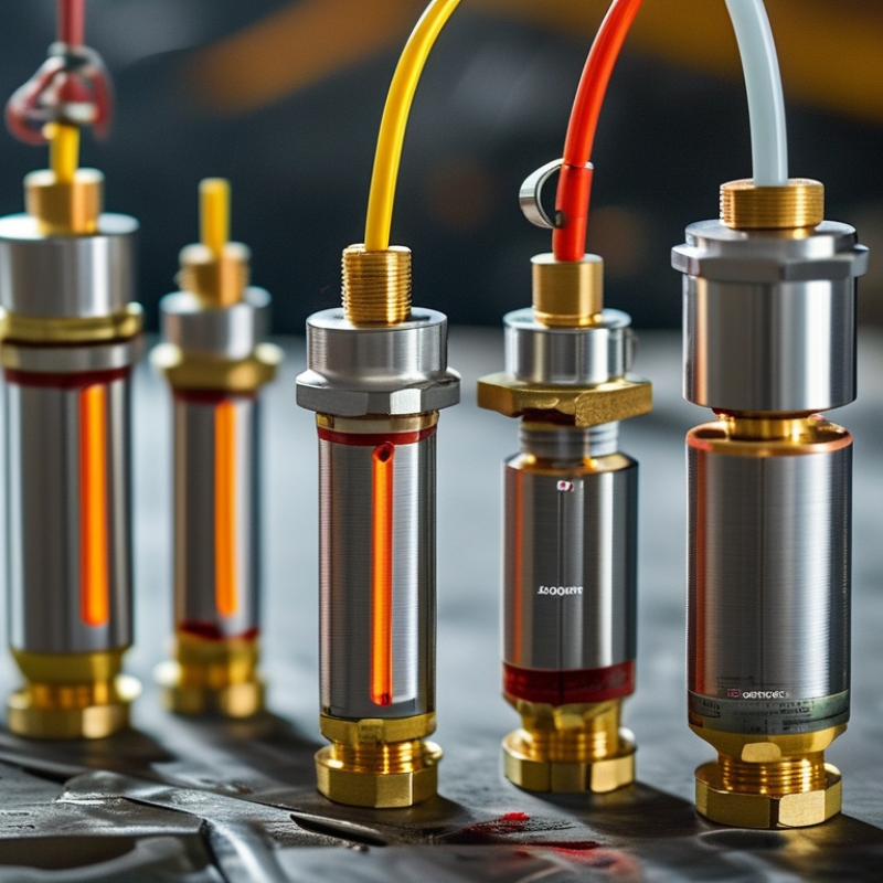
High temperature pressure sensors measure pressure in hot environments where ordinary sensors may drift, fail, or lose accuracy. They are used near engines, furnaces, turbines, chemical reactors, and heated test equipment. “High temperature” has no universal limit. It depends on the sensor design, process conditions, and exposure time. Some sensors tolerate heat directly, while others use a cooling stem or remote diaphragm.
These sensors usually combine heat-resistant materials, protective seals, and pressure-sensitive elements. Some designs separate the sensing element from the hottest zone. This arrangement reduces thermal stress but may slow the response. When choosing one, check the continuous temperature rating, short-term temperature limit, pressure range, accuracy, response time, and electrical output. Do not rely only on a product’s maximum value. Continuous operation near that limit can shorten service life.
Installation experience also matters. A sensor beside a glowing pipe may receive more radiant heat than expected. Insulation can help, but it may trap heat around the housing. I have seen readings change after a small mounting adjustment. That detail is easy to miss. Also inspect vibration, moisture, corrosive gases, and pressure spikes. A sensor that performs well in a laboratory may behave differently in a crowded production line. Calibration should be checked at realistic temperatures, although this step is sometimes overlooked. No sensor is perfect.
High temperature pressure sensors are selected according to the sensing technology, continuous operating temperature, pressure range, chemical compatibility, and whether the application measures static or dynamic pressure. The chart shows representative continuous temperature limits for common sensor technologies.
Selection guidance: Silicon and ceramic sensors are suitable for moderate temperatures, while thin-film metal and silicon-on-insulator designs support higher continuous temperatures. Piezoelectric sensors can withstand very high temperatures and are well suited to dynamic pressure measurement, but they are generally not intended for long-term static pressure measurement without specialized signal conditioning.
High-temperature pressure sensing begins with the real process temperature, not the catalog maximum. The U.S. Department of Energy reports that process heating represents about 51% of manufacturing energy use. This makes stable pressure measurement valuable for efficiency and safety. Check the continuous temperature rating, short-term overload rating, and thermal cycling limit. A sensor rated for 200°C may fail during repeated 240°C cleaning cycles. That detail is easy to miss.
Accuracy is only one part of performance. Review total error across temperature, including zero shift, span drift, hysteresis, and repeatability. IEC 60770-1 recommends evaluating industrial transmitters under defined reference conditions. Those conditions rarely match a vibrating furnace or a pipe with rapid pressure changes. Response time also matters. A slow sensor can hide a dangerous pressure spike. For harsh systems, select wetted materials that resist oxidation, corrosion, and process chemicals. Verify the pressure port design, sealing method, and electrical protection rating. I have seen specifications look impressive until thermal expansion changed the zero point.
Tips: Compare total error, not headline accuracy. Ask for temperature-drift data. Test the sensor beside the actual mounting point. Leave margin above normal temperature and pressure. Do not assume a cooling diaphragm seal solves every installation problem. It may increase response delay. That trade-off deserves measurement, not guesswork.
Sources: U.S. Department of Energy, Industrial Decarbonization Roadmap, 2022; IEC 60770-1, Industrial-Process Measurement and Control.
Choosing a high-temperature pressure sensor starts with the fluid, not the temperature rating. A sensor facing hot oil needs different wetted materials from one measuring steam or corrosive gas. Stainless steel may suit many clean processes, but it is not a universal answer. Check the diaphragm, pressure port, welds, and sealing elements together. One weak material can limit the entire assembly. For aggressive media, consider nickel-based alloys, ceramic sensing elements, or protective isolation structures. Their value depends on chemistry, pressure, and exposure time. Short peaks and continuous heat are not equivalent. Neither are dry heat and saturated steam. Keep that distinction visible.
Thermal expansion deserves equal attention. Dissimilar metals can create mechanical stress during repeated heating and cooling. A seal that performs well at room temperature may harden, leak, or lose elasticity near the process limit. Select insulation and cable materials for the actual temperature at the connector, not only at the sensing point. A field review once focused on 300°C, while a vibrating cable transition caused the actual failure. That detail is easy to miss. Test material compatibility with real media, pressure cycles, and installation orientation. Review calibration drift after heat soaking. If data is limited, choose a conservative margin and document the reason. No material choice is perfect. It must remain stable, clean, and serviceable over time.
How to Choose High Temperature Pressure Sensors?
What Installation Conditions Affect Measurement Accuracy?
Choosing a high temperature pressure sensor starts with the installation environment, not the catalog range. Heat reaches the sensing element through the process connection, tubing, and mounting hardware. A sensor rated for 300°C may still drift during rapid temperature changes. That difference matters.
Mount the sensor away from direct flames, radiant furnace walls, and turbulent flow whenever possible. Use a suitable standoff, cooling element, or impulse line to reduce heat transfer. Keep the connection short enough to limit pressure lag, but not so short that electronics sit beside the hot zone. During field checks, I look for discolored insulation, loose fittings, and tubing vibrating against steel frames. Small mechanical problems often become large measurement errors.
Ambient temperature also deserves attention. A sealed enclosure can trap heat around the sensor during long production cycles. Provide ventilation without allowing dust or moisture to enter. Pressure ports should face downward where condensation may collect. Use compatible sealing materials, and tighten fittings to the specified torque. Excessive force can distort the diaphragm.
Calibration should match the installed position and operating temperature. Check the zero point after thermal stability, not immediately after startup. Check the zero. I have seen readings improve after this simple delay. Still, installation practice is not perfectly repeatable. Record the mounting angle, line length, temperature, and vibration level when readings seem inconsistent.
| Installation Condition | What to Check | Typical Accuracy Risk | Recommended Installation Practice | Sensor Selection Consideration |
|---|---|---|---|---|
| Process temperature | Confirm the maximum process temperature and the temperature at the sensing diaphragm, not only the pipe temperature. | Temperature can shift zero and span. Operation outside the specified compensated range may cause significant measurement error or permanent damage. | Use a diaphragm seal, cooling element, impulse line, or remote mounting arrangement when the process temperature exceeds the sensor rating. | Select a sensor with a rated process-temperature range and a temperature-compensated accuracy specification. |
| Ambient temperature at the electronics | Measure the temperature surrounding the transmitter housing and cable entry. | Electronics drift increases when ambient temperature approaches the upper or lower operating limit. | Keep the electronics away from radiant heat, provide ventilation where appropriate, and avoid direct contact with hot surfaces. | Compare total accuracy over the actual ambient range, including thermal drift and long-term stability. |
| Thermal shock and rapid temperature change | Identify steam cleaning, cold flushing, batch changes, startup, shutdown, and other fast thermal transitions. | Unequal heating of the diaphragm and housing can create temporary zero shifts and mechanical stress. | Use gradual warm-up and cool-down procedures; avoid directing cold liquid onto a hot sensor or seal. | Choose a construction and diaphragm material suitable for the expected thermal cycling frequency. |
| Pressure impulse line length and layout | Check line length, internal diameter, bends, elevation changes, and possible blockage or leakage. | Long or restricted lines can slow response, attenuate pressure changes, and retain gas, liquid, or condensate. | Keep impulse lines short where practical, use consistent slopes, eliminate unnecessary bends, and leak-test all connections. | For fast dynamic measurements, consider direct mounting or a remote seal instead of a long impulse line. |
| Condensation, trapped gas, or trapped liquid | Determine whether the measured medium is a gas, liquid, steam, or a two-phase mixture. | Condensate in gas service and gas pockets in liquid service can produce hydrostatic head errors and unstable readings. | For gas service, avoid low points where liquid can collect; for liquid service, avoid high points where gas can collect. Use suitable drains or vents. | Select a sensor and seal system compatible with the process phase and expected condensation conditions. |
| Mounting orientation and hydrostatic head | Check the vertical distance between the pressure tap and the sensor diaphragm, especially in liquid-filled lines. | The fluid column creates a static pressure offset. The error depends on fluid density and elevation difference. | Install the sensor in the recommended orientation and compensate the zero for the actual elevation and process-fluid density. | Prefer a pressure range and zero-adjustment capability that allow the expected static head to be corrected. |
| Vibration and mechanical stress | Inspect pumps, compressors, reciprocating equipment, pipe resonance, and unsupported tubing. | Vibration can create fluctuating output, loosen fittings, fatigue wiring, and accelerate sensor aging. | Use rigid supports, flexible connections where appropriate, vibration isolators, and adequate strain relief for cables. | Choose a sensor with a vibration rating suitable for the measured frequency and acceleration environment. |
| Pressure pulsation and surge | Identify pump strokes, valve closures, compressor cycles, water hammer, and startup pressure peaks. | Repeated overpressure or rapid pulses can overload the sensing diaphragm and produce noisy or drifting output. | Install snubbers, restrictors, dampers, or suitable process protection while ensuring that response time remains acceptable. | Select a proof-pressure and burst-pressure rating above the highest credible transient, not merely the normal operating pressure. |
| Corrosive, abrasive, or viscous media | Review chemical compatibility, particle loading, viscosity, crystallization, and cleaning chemicals. | Corrosion, erosion, coating, or plugged ports can change diaphragm behavior or isolate the sensor from the true pressure. | Use compatible wetted materials, protective coatings, flush diaphragms, purge systems, or remote seals where required. | Base material selection on the complete chemical and temperature exposure, including cleaning and sterilization cycles. |
| Moisture, ingress, and cable routing | Check washdown, rain, condensation, humidity, cable glands, conduit, and enclosure orientation. | Moisture can cause insulation leakage, corrosion, unstable signals, and eventual electronic failure. | Use correctly rated enclosures and cable glands, create drip loops, tighten entries properly, and prevent water from entering through the cable. | Select an ingress-protection level appropriate to the installation environment and maintenance procedure. |
| Electrical interference and grounding | Identify variable-frequency drives, motors, high-current cables, switching devices, and ground-potential differences. | Electromagnetic interference can introduce noise, intermittent readings, or communication faults. | Separate signal and power wiring, use properly shielded twisted pairs, ground the shield according to the system design, and avoid ground loops. | Choose an output and wiring method compatible with the control system and specified electromagnetic-environment requirements. |
| Pressure range and operating point | Compare normal pressure, calibration points, negative pressure, overloads, and transient peaks. | A range that is much higher than necessary reduces usable resolution and makes small pressure changes harder to distinguish. | Select the narrowest range that safely covers normal operation and all credible overpressure conditions. | Check whether accuracy is specified as a percentage of full scale, span, or reading; these definitions are not interchangeable. |
| Calibration and zero verification | Determine the required calibration interval and whether the sensor can be isolated safely for testing. | Zero drift, span drift, contamination, and changes in installation conditions can gradually reduce accuracy. | Allow isolation, venting, and reference-pressure testing; verify zero after installation and after major temperature or process changes. | Evaluate long-term stability, adjustment capability, and the uncertainty of the complete measurement chain. |
Note: Actual accuracy depends on the complete sensor, process connection, installation, signal wiring, calibration method, and operating environment. Always use the manufacturer’s published temperature, pressure, materials, ingress, vibration, and accuracy specifications for final selection.
How to Choose High Temperature Pressure Sensors?
Calibration deserves more attention than a single accuracy number. Ask whether the sensor was calibrated at its actual operating temperature, not only at room temperature. Request traceable calibration records, test points, and stated uncertainty. A sensor may read accurately at 25°C yet drift near 300°C. Compare readings during pressure increases and decreases. Hysteresis can reveal mechanical stress that a basic certificate misses. Do not trust one reading.
Safety depends on the complete installation. Check the maximum working pressure, burst pressure, temperature range, and connection materials. Confirm that seals, cables, and protective housings tolerate the same environment. A sensor rated for high temperature may still fail when exposed to vibration, steam, or corrosive gases. Include thermal barriers or cooling sections when required. Keep wiring away from hot surfaces and inspect fittings for small leaks.
Long-term reliability is harder to prove. Review drift data, pressure-cycle results, response time, and maintenance requirements. Ask how the sensing element behaves after repeated thermal expansion and contraction. In field work, I have found that easy access often matters as much as impressive specifications. Replacement calibration can be delayed by poor installation design. That is an uncomfortable detail. Also, laboratory results may not represent your process exactly. Test a sample under realistic temperature cycles before wider deployment, and record changes over time.
As a specialist in environmental and flow sensor technology, ScioSense enables companies to use the planet’s resources more sustainably, helping to create a healthier future for all.